Started a consulting company. Free tools and easy to follow guidelines will be available online for free very shortly. Go to www.pythonbird.com
Tuesday, May 12, 2009
Environmental Consulting
Posted by slavster at 10:15 AM 0 comments
Labels: consulting, environmental, GHG
Thursday, April 30, 2009
Corrosion in a tank
One of the most common corrosion problems you will be asked to solve is how a tank, open to the atmosphere, corrodes and how you can control the rate of corrosion by simply covering the tank and regulating the pressure. Here is what is usually given:
T = 25oC
P = 1 atm
Corrosion Rate = 2.4 g Fe/cm2-yr
Say that O2 reduction is limited by mass transfer of dissolved O2 to the tank wall and the solubility of dissolved oxygen can be related to its partial pressure:
CO2 = 1.28x10⁻³ PO2
The partial pressure is in atm and the concentration is in mol/L. The oxidation of Feo is kinetically controlled in the Tafel region:
iO = 0.8x10⁻⁸ amp/cm2
Tafel Slope = 1/120 mV-1
ne = 1
Acceptable Corrosion Rate = 0.01 g Fe/cm2-yr
CFe2+ = 10-6 mol/L at all times
Feo -> Fe2+ + 2e-, -0.440 VSHE
And you are asked to determine the total pressure the headspace should be evacuated to to attain the acceptable corrosion rate.
Solution:
You are given that the O2 reduction is mass transfer limited so right away you can modify your general equation from:
To:
From the given information you can find the concentration of dissolved oxygen in the bulk as well as the current from the Faraday’s law. Please see my earlier posts for more information on how to use Faraday’s to calculate current given a deposition rate.
From the given relationship between pressure and concentration, you can determine the bulk concentration of dissolved oxygen:
Now that you have all the required information, you can calculate the km value.
The next step is to determine the current density at the acceptable corrosion rate using the same line calculation as before:
Looking at the mass transfer limitation equation, we only have 1 unknown – the bulk concentration of dissolved oxygen, which is calculated via:
Great, now we can use the given relationship for partial pressure of oxygen and concentration to determine the partial pressure of oxygen in the headspace:
This is not the end, because oxygen only accounts for 21% of the composition of air, so the total headspace pressure has to be:
I apologize how bad some of the equations look. I really have to look into finding a new blog editor. If this has helped you in any way, please click on some of the ads.
Posted by slavster at 1:03 PM 0 comments
Saturday, March 14, 2009
Partial Differential Equations – Separation of Variables
I received a great tutorial on how to apply separation of variables to solve a partial differential equation. I copied some of the equations as images because my generic editor cannot handle some symbols. The example is the following:
A uniform rod of length L with Finite Ends at Zero Temperature.
Equation given:
For 0 < x < L and t >= 0
Boundary Conditions:
- U(0, t) = 0 … (2)
- U(L,t) = 0 … (3)
Initial Conditions – U(x,o) = fo(x) … (4)
- The PDE is linear and homogeneous
- The boundary conditions are also linear and homogeneous
Separation of variables:
Adjust 5 so that it can be substituted into 1:
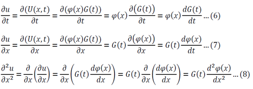
Substitute 6 and 8 into 1:
Function of only time = Function of only space
Both sides of the equation must equal to the same constant, called a separation constant. We get:
And
Equation 11 is the time depended equation and will be solved first. This is a first order linear homogeneous ODE and can be solved using the method of separation of variables.
The final solution will then be:
Analysis of possible values of lambda:
- If lambda > 0 the temperature will exponentially decay with time
- If lambda < 0 the temperature will exponentially increase with time
- If lambda = 0 the temperature will stay constant
Only lambda => 0 makes sense as the temperature is not meant to grow to infinity.
Equation 12 is the space dependent equation. As equation 12 is a linear, second order, homogeneous ODE with constant coefficients, a method of constant coefficients can be used in order to solve that equation.
Substitution of 14 and 15 into 12 gives:
Equation 16 has numerous solutions, which all depend on the value of lambda:
Evaluate each of the cases
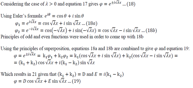
Lambda > 0
Lambda = 0
The solution of r=0 can be used here, or double integration can be used to solve equation 12
Substitution of equations 19, 20 and 13 into equation 5 gives the following general solution:
The boundary conditions now have to be applied:
Lambda > 0
Using Equation 22 in 19:
Using Equation 23 in 19:
Solving Equation 24:
Lambda is now written with a subscript n as it could take on multiple values due to infinite number of possible solutions of the sin function.
Lambda = 0
Application of 22 in 20:
Application of 23 in 20:
So either L is zero or A is zero. Having zero length defeats the purpose of the problem so A = must be true.
Using all the values determined from the boundary conditions in equation 21:
Where C’ = CE
We now use the initial conditions and get:
So then:
We can apply the following identity:
Using equations 29 and 30, the left side of 31 becomes:
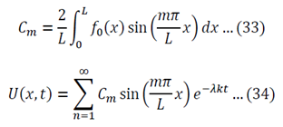
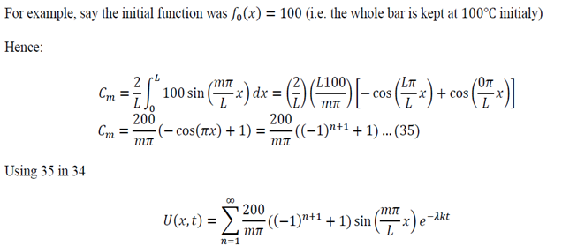
To generalize:
Posted by slavster at 5:22 PM 0 comments
Labels: Differential Equations, Examples, Partial Differential Equations
Saturday, February 7, 2009
Conversion Table
I have an exam next week for which I have to bring my own conversion table. I quickly compiled one and decided to upload it. Click on the link to download the pdf and print it. This is just a basic conversion table, nothing fancy.
Posted by slavster at 8:11 PM 0 comments
Labels: conversion table, Unit Conversions
Friday, February 6, 2009
Emission Factors, Part 2
I found some time to upload another part of the emission factors I have. If you have any comments, or questions, leave a comment. Check out the previous post for the calculations.
Calorific Values, Petroleum-based fuels
| Fuel | (GJ/kg) | (MMBTU/lb) |
| Crude Oil | 0.046 | 0.020 |
| Gasoline | 0.047 | 0.020 |
| Aviation Gasoline | 0.048 | 0.021 |
| Distillate Fuel Oil No. 1 | 0.046 | 0.020 |
| Distillate Fuel Oil No. 2 | 0.046 | 0.020 |
| Distillate Fuel Oil No. 4 | 0.046 | 0.020 |
| Jet Kerosene | 0.0469 | 0.0202 |
| Kerosene (Other) | 0.047 | 0.020 |
| LPG | 0.050 | 0.022 |
| Naphtha | 0.047 | 0.020 |
| Lubricants | 0.043 | 0.019 |
| Waxes | 0.046 | 0.020 |
| Shale Oil (liquid) | 0.038 | 0.016 |
| Oil Shale | 0.010 | 0.004 |
Carbon Content, Petroleum-based fuels
| Fuel | (kg C/GJ) | (Thousand BTU/lb) |
| Crude Oil | 19 | 44 |
| Gasoline | 18 | 42 |
| Aviation Gasoline | 17.9 | 41.6 |
| Distillate Fuel Oil No. 1 | 19 | 44 |
| Distillate Fuel Oil No. 2 | 19 | 44 |
| Distillate Fuel Oil No. 4 | 19 | 44 |
| Jet Kerosene | 18.5 | 43 |
| Kerosene (Other) | 18.6 | 43.3 |
| LPG | 16 | 38 |
| Naphtha | 19 | 44 |
| Lubricants | 19 | 44 |
| Waxes | 19 | 44 |
| Shale Oil (liquid) | 19 | 44 |
| Oil Shale | 28 | 65 |
Posted by slavster at 3:14 PM 0 comments
Labels: CO2 Emissions, Emission Factors, GHG, Petroleum Fuels
Friday, January 23, 2009
Emission Factors
Over the last few years I have performed a lot of emission calculations and have found it frustrating that I had to spend hours searching for emission factors. I recently decided to compile a few short tables and carry them with me on a USB stick for easy access. Here they are. All the values can be found on the IPCC’s EFDB site or through a search engine. Different sources may have different values, but they should not be too far off. I cannot recall and reference all the websites I have used, but if I remember correctly, the values are from the late 90’s and early 2000’s. Since I have to do some editing and don’t have much time, I will break up the factors into a couple of posts.
Using the tables
CO2 = (Amount of fuel used) * (Calorific Value) * (Carbon Content) * (Oxidation) * 3.66
Oxidation values are usually given in percentages and are around 98% to 100%. I usually use 99% to be safe. 3.66 comes from the ratio of Carbon to Oxygen in CO2. If you do not understand why you need 3.66, try doing a line calculation and write out all the units. You are calculating the emission with respect to carbon, but don’t forget that you are emitting CO2 and not just C. Chances are you have come across simple conversion factors which take you from Fuel Used to CO2 emitted. The above calculation takes into account a few more factors and may vary slightly from the simple conversion factors. When doing the calculation remember to keep in mind the units.
Calorific Values, Natural gas-based fuels
| Fuel | (GJ/kg) | (MMBTU/lb) |
| Natural Gas | 0.051 | 0.022 |
| Methane | 0.0556 | 0.0239 |
| Ethane | 0.0519 | 0.0223 |
| Propane | 0.0504 | 0.0217 |
| Butane | 0.0495 | 0.0213 |
| Isobutane | 0.0495 | 0.0213 |
| n-Butane | 0.0494 | 0.0213 |
| LNG | 0.052 | 0.022 |
Carbon Content, Natural gas-based fuels
| Fuel | (kg C/GJ) | (Thousand BTU/lb) |
| Natural Gas | 14 | 33 |
| Methane | 13.5 | 31.3 |
| Ethane | 15.4 | 35.8 |
| Propane | 16.2 | 37.7 |
| Butane | 16.7 | 38.9 |
| Isobutane | 16.7 | 38.9 |
| n-Butane | 16.8 | 38.9 |
| LNG | 16 | 38 |
Posted by slavster at 6:04 PM 0 comments
Labels: CO2 Emissions, Emission Factors, GHG, Natural Gas Fuels
Saturday, January 17, 2009
Hall-Heroult Process
Hall-Heroult Process
The Hall-Heroult process is a continuous industrial process for the production of aluminum. The process is carried out in a molten cryolite salt bath. For more information on how the process works take a look at the wikipedia entry here. To calculate Al production, there are several reactions that one must look at. The first set of reactions is the dissolution of Al2O3 in the bath:
Na3AlF6 -> 3Na+ + AlF63-
and
4AlF63- + Al2O3 -> 3Al2OF62- + 6F-
The production of Al is at the cathode through:
Al2OF62- + 6e- -> 2Alo + 6F- + O2-
And at the anode:
C + 2O2- -> CO2 + 4e-
For the ease of calculating Al production, the reactions at the cathode and anode can be simplified to:
Al3- + 3e- -> Alo at the cathode
and
C + 2O2- -> CO2 + 4e- at the anode
Aluminum production:
Textbooks on Electrochemistry may use different notation for the stoichiometry so be careful. The notation used for this case is:
aj = species on opposite side of e-
bj = species on the same side as e-
ne = electrons
Keeping this in mind you will have aAl = 1, bAl3- = 1 and ne = 3. The Faraday`s law can be written in several different ways, but the one used here for the production of Al is:
I = -(ne/aAl)*F*(dnAl/dt)
where: I = current at the electrode (the cathode is this case)
F = Faraday`s constant, 96,485.3 C mol-1
dnAl/dt = the production of Al for a given time period
Note: there is a negative sign, because electrons are used up. aAl in the denominator has to be substituted with bAl3- if calculating the required Al3- ions for the production of Alo.
The equation can be changed to give the production of Al to:
dnAl/dt = (|- Icathode|*aAl)/(ne*F) in mol/s
Why is it in mol/s? Take a look at the I/F term. The units for current are Amperes, which are C sec-1 and C mol-1 for the Faraday`s constant. So (C sec-1)/(C mol-1) = mol sec-1. Also, why is the current |-Icathode|? It is that way, because we know that I = I anode = |-Icathode|.
At this point you can put all of the knowns in the above equation with I being the only unknown:
dnAl/dt = (I*1)/(3*96,485.3) = I/289,455.9 mol/s
Using the molecular weight of Al, we can convert the units to g/s:
dnAl/dt = (I/289,455.9)*26.9815 g/mol = I/10,727.94 g/s
For example, if we have current of 150,000 amps, the production rate will be:
dnAl/dt = 150,000/10,727.94 = 13.98 g/s
Don`t forget that there might be some side reactions taking place at the cathode, which will reduce the current at the cathode used in the production of Al. If the current efficiency is given, multiply the total current by it to obtain the cathodic one.
If you liked what you read, please click on some of the ads and help me pay my student bills.Posted by slavster at 4:15 PM 0 comments
Labels: Al production, aluminum, aluminum production, hall heroult, hall heroult example, hall-heroult process, heroult process


